for educators
this is prep work, not the workshop
this page is for whoever is setting up kits ahead of time, installing CircuitPython, flashing code, and testing hardware. attendees never see any of this. by the time someone sits down at the workshop, their kit is already fully preloaded and working. all they do is tweak the code, wire the button, and build their enclosure, see workshop day for that shorter version.
what you'll need: an Adafruit RP2040 Feather ThinkInk, a 2.13" 212×104 flexible monochrome eInk display (ILI0373 chipset), a USB-C cable, and a computer to program from. for a full parts list and alternatives, see resources.
quick reference: flashing a batch
if you've already been through the full setup once and just need a fast checklist for preparing multiple units, here it is. full detail on each step is below.
- disconnect the eInk display before entering bootloader mode, for every board.
- flash CircuitPython 10.x, if it isn't already installed.
- copy
lib/adafruit_il0373.mpyandlib/adafruit_display_text/onto the board. - copy the final code.py onto the board.
- reconnect the display and test: the intro screen should appear, press the button once, and confirm it starts cycling through messages with the countdown printing on the serial console.
keep a simple tally as you go, which units pass cleanly versus need troubleshooting. that tells you a lot about consistency across the batch before the workshop itself.
0. seat the display
before anything else, the eInk display's ribbon cable needs to be seated into the Feather's display connector. this only needs to happen once per kit.

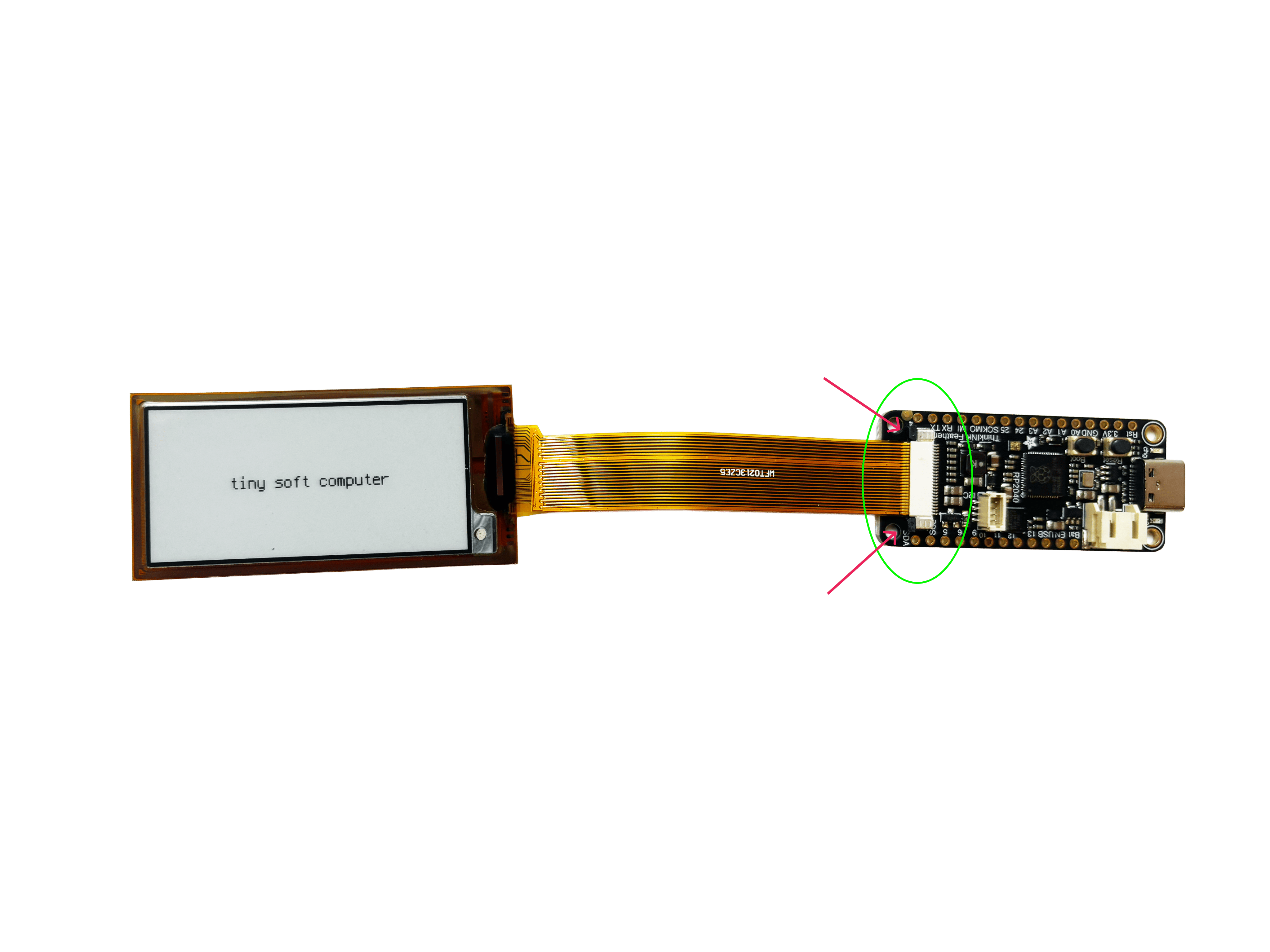
the latches need to be open before you insert the cable, and closed firmly afterward to hold it in place. the cable only fits one way, don't force it if it's not sliding in easily.
1. install CircuitPython
before you start: disconnect the eInk display from the Feather. having it connected can interfere with the board entering bootloader mode. reconnect it once CircuitPython is installed.
- unplug the board completely.
- press and hold the BOOTSEL button (this is the button on the board itself, labeled BOOT or BOOTSEL, not the reset button).
- while still holding it, plug in the USB-C cable.
- wait a second or two, then release the button. this "boot on start" method is more reliable than double-pressing reset while already powered on.
- a drive named
RPI-RP2should appear. check your file browser (Finder on Mac, File Explorer on Windows) under "Locations" or "This PC", it shows up like a USB flash drive. - go to circuitpython.org, click the Downloads tab in the nav, and search for your board: "Adafruit Feather RP2040 ThinkInk". don't pick a generic RP2040 file, other variants have different pin mappings.
- choose the stable release (10.x), and download the single
.uf2file. it will land in your computer's Downloads folder unless you chose a different save location. - open your Downloads folder, find that
.uf2file, and drag it onto theRPI-RP2drive. - the board restarts automatically. the drive is now named
CIRCUITPY, that means CircuitPython is installed. - now reconnect the eInk display.
if the RPI-RP2 drive never appears: confirm the display
is disconnected, try a different USB-C cable (some are charge-only),
try a different port, or unplug fully and retry the BOOTSEL sequence.
2. add the required libraries
go to the CircuitPython
Library Bundle page, and download the latest zip
matching your exact CircuitPython major version (check
boot_out.txt on your CIRCUITPY drive if you're not sure
which version you're running, e.g. "10.x"). bundle releases get
periodic bug fixes, so grabbing the newest one for your version
line, rather than an old cached download, helps keep all your kits
consistent. it will land in your Downloads folder.
unzip it, then from inside the unzipped folder's lib
subfolder, drag these two items onto your CIRCUITPY drive, into a
folder there also named lib (create that folder if it
doesn't exist yet):
adafruit_il0373.mpyadafruit_display_text(folder)
names must be exact, underscores not hyphens. a mismatched name is the most common reason a library fails to import.
3. add the code
when you first open code.py on a fresh CIRCUITPY drive,
you'll likely see a single line already there:
print("Hello World!"). that's just a default test file,
not part of this project. delete it, then paste in the real code
below.
- if you don't already have a code editor for CircuitPython, install Mu Editor, a free, beginner-friendly editor built specifically for it. you'll use it to edit and paste in code, and to view the serial console (see using the serial monitor below).
- copy the code onto your CIRCUITPY drive as
code.py, replacing whatever was there. (use the copy button on the code page to grab the whole file at once.) - the board should auto-run it. if not, press reset once.
- watch the serial console as it runs, it prints its progress at each step.
- wait for "refresh complete" before judging what's on screen. e-ink flickers through intermediate frames mid-refresh, this can look like smudging and is completely normal.
hardware: where things connect

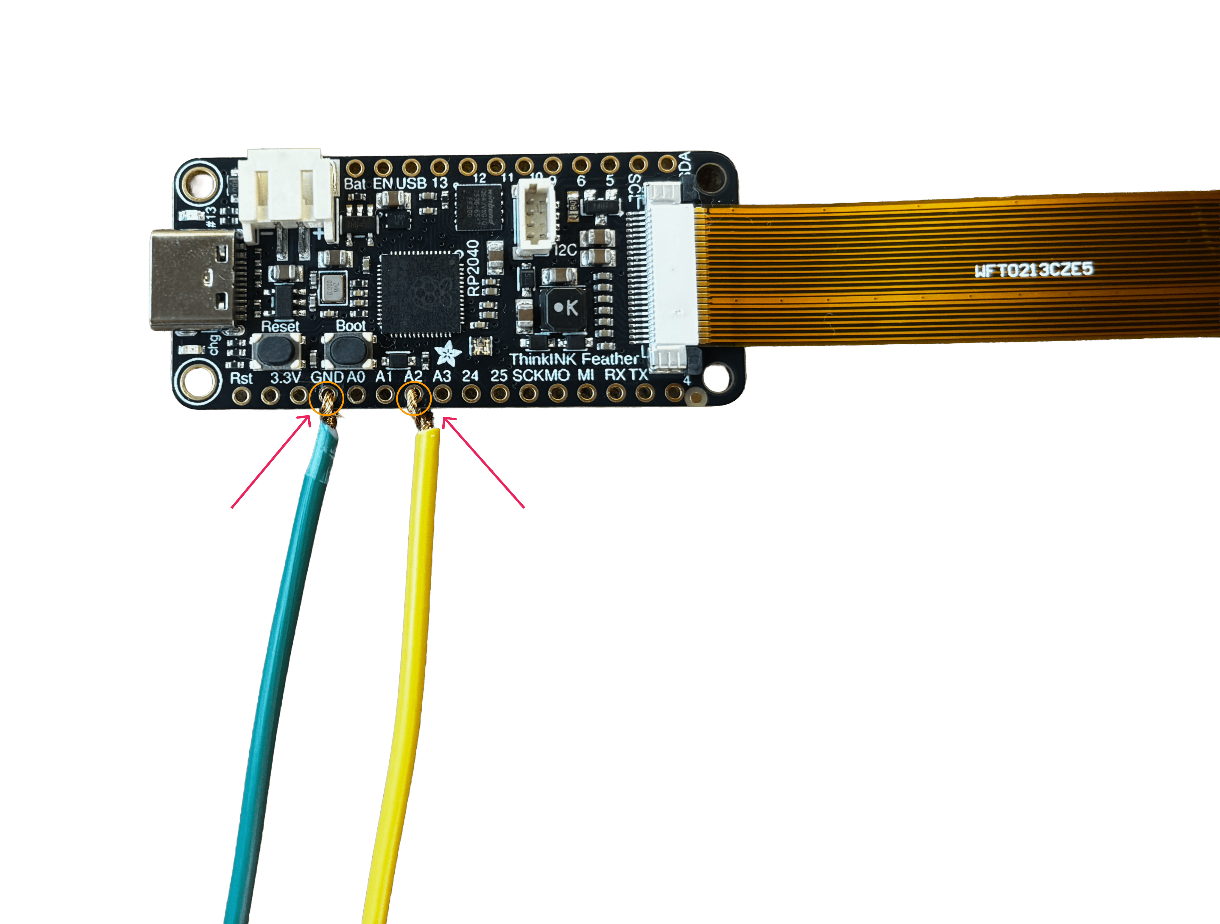
the button needs two wires: one leg to pin A2, the other
leg to any GND pin. no resistor is needed, the code
already uses the board's internal pull-up resistor.
the eInk display connects via its 24-pin ribbon cable into the Feather's display connector, this only fits one way, don't force it.
using the serial monitor
the serial console (accessed through the REPL in Mu, or any serial terminal) shows live text output from the board while your code runs. this project's code prints a line at almost every step ("starting up", "display ready", "showing: ...", etc.), specifically so you can see exactly where something goes wrong instead of guessing.
if a kit isn't behaving, check the serial console first, before touching any wiring. an error message here tells you far more than staring at the display ever will.

troubleshooting notes
real issues we hit while testing, and what fixed them.
why the display can't refresh quickly
this isn't a bug, it's physics. e-ink works by physically moving charged ink particles inside each pixel, not by lighting up transistors. that movement takes real time, and it can't be rushed by better code.
the manufacturer's own datasheet for this exact panel states it
directly: "each update interval time should be minimum at
180 seconds" for the panel's rated 5-year, 1,000,000-cycle
lifespan to hold. the CircuitPython driver enforces this,
attempting a refresh before that window passes raises a
RuntimeError: Refresh too soon, on purpose.
it's possible to override this in code (a refresh_time
parameter exists), but doing so doesn't make the physical ink
move any faster, it just lets the code ask again sooner than the
panel can actually deliver. the likely result is a ghosted or
incomplete image, and real wear on the panel over repeated
cycles. we chose not to override it.
this is exactly the kind of limitation this workshop asks you to design with, not around. rather than fighting the display's pace, the wait itself becomes part of what pressing the button means, not a flaw to hide.
code runs with no error, but nothing shows
bitmaps must be created with value_count=2, not
1. using 1 technically creates a
zero-bit bitmap that can silently fail to render, even though
the code runs without error. this was the root cause of a lot
of confusing "it's not working" testing, not faulty hardware.
screen looks blurry or smudged
e-ink flickers through several frames during a refresh. don't judge the screen until the code confirms the refresh is complete. checking mid-refresh looks exactly like a real problem, and usually isn't one.
the RPI-RP2 drive won't appear
disconnect the eInk display before entering bootloader mode. the display connected during this step can prevent the drive from showing up at all.
SyntaxError referencing <stdin>
not a code problem. usually a stray keypress sent into the REPL prompt directly. press Ctrl+D to reload, or press the physical reset button, and try again.
a display seems consistently faulty
before assuming hardware failure: re-test with the latest known-good code first. an earlier bug in our own script caused some units to look broken when they weren't. if it's still inconsistent after that, isolate by swapping the display to a different board, and the board to a different display, whichever component the problem follows is the actual fault.
OLED version: ValueError: Unable to find I2C Display at 3c
this is an OLED-alternative issue, not an eInk one. most SSD1306
OLEDs answer at I2C address 0x3c, but the exact
address is set by a jumper on the OLED board itself, so some
units answer at 0x3d instead. across a batch of
kits, expect a mix.
the current OLED code handles this automatically: it scans the I2C bus at startup and uses whichever address actually responds, so this shouldn't come up if attendees are running the latest version from the code page.
if it does come up anyway, it almost always means the STEMMA QT cable isn't fully seated on one end, not a wrong address. reseat both ends first. to check what's actually on the bus, run this in the REPL:
import board
i2c = board.STEMMA_I2C()
while not i2c.try_lock():
    pass
print([hex(x) for x in i2c.scan()])
i2c.unlock()
an empty list means nothing is responding, check the cable. a different address showing up means that's the OLED, and the auto-detect logic will pick it up on its own.
this display holds its image with no power needed. once it shows text, you can even unplug it and the image will remain.
this is a living document. it gets updated as we test more units and find new issues, so it stays accurate for whoever builds one after us.
for a full parts list and classroom-friendly alternatives, see resources.